Monday 27 December 2010

Light Canvas - LEDs 2: Choosing and Testing

After shopping around a bit online, I bought 100 3mm and 100 5mm warm white diffuse LEDs - buying in bulk for this project and the next. As well as size, the two models differ in viewing/beam angle, and brightness. Two types to experiment with is manageable, and should let me play with brightness/diffusion.

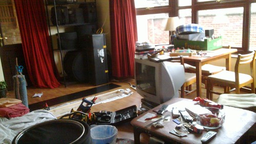
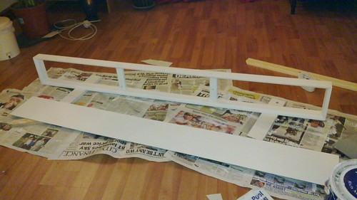
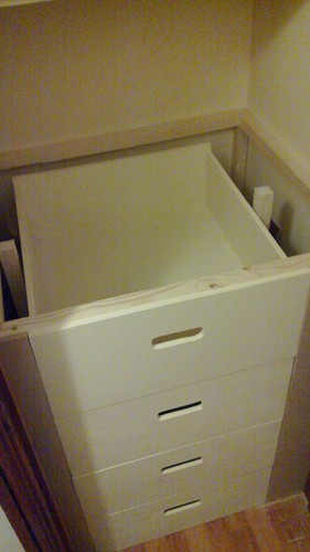
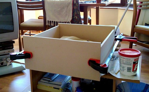
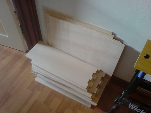
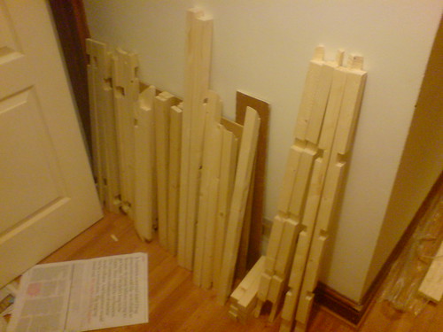
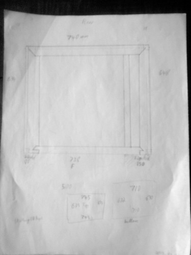
One hundred pounds worth of LEDs don't come in a big box...

The LEDs arrive

5mm & 3mm LEDs

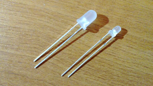
(I should've included something for scale in those pics. Nevermind.)

Plan of frame and LEDs
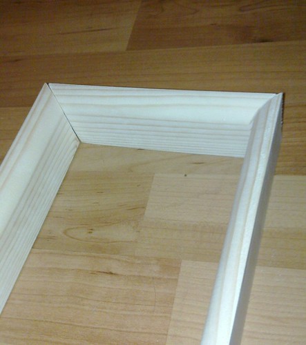
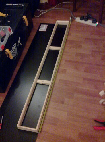
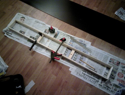
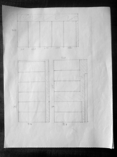
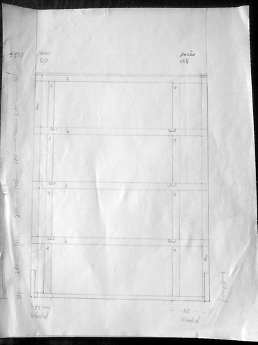
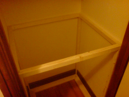
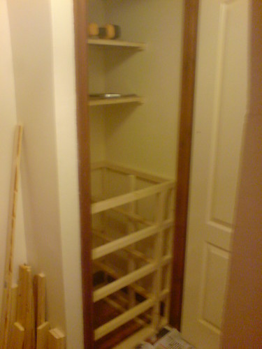
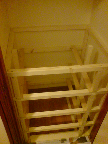
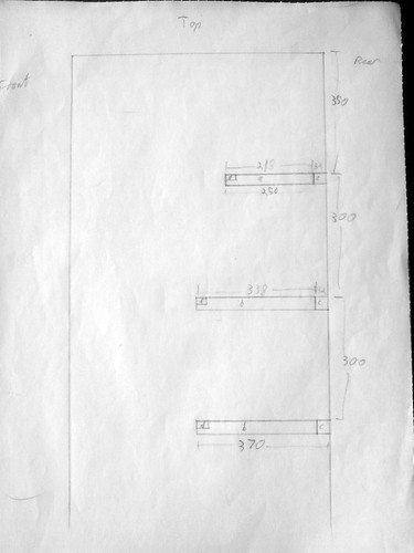
Once I had the frame put together, it occurred to me that three or four LEDs could be put serially in little columns on perfboard, each with their own resistor and connection to the power supply - something like the plan on the right.

Lets remove some unknowns: I want it bright, and nine columns of four LEDs should be pretty good, I reckon.

I've already got wires, resistors, and a breadboard so now I can do some testing.

For prototyping, I attached a couple of crocodile clips to a mains adaptor at it's lowest setting and ran that through a breadboard with one 5mm LED and the recommended resistor, to check that the basics were working, then bumped up the voltage to 12, as I plan to use in the final piece. That worked fine, so I put four LEDs in series and, using an online LED resistor calculator, found a (lower) value of resistor, accommodating the greater voltage drop caused by the additional LEDs (assuming a 2V drop per LED).

If I'm to learn anything here, I ought to figure the resistor stuff out myself, rather than using the online calculator.  For the moment though, I think I get the gist:
  • Power source provides a electrical potential difference,
  • generation of light by each LED is an electrical load, which uses some of that potential, hence
  • voltage drop gives a lower effective voltage over the circuit, hence
  • a lower value resistor is necessary.
I need to do some testing to see how this fits in with Ohms law so I understand it a bit better - but not right now, as there's more hands-on stuff first!

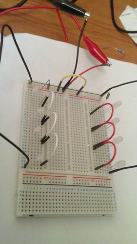
I was quite happy with the 5mm LEDs in a row of four, so did the same with the 3mm LEDs. Here's the breadboard:
Breadboard close-up

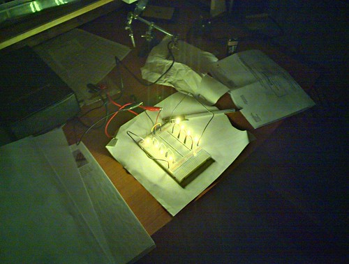
...here it is lit up:
Bare LEDs

...with 80gsm paper as a diffuser:
Using 80gsm paper as a diffuser

...and with 160gsm card as a diffuser:
Using 160gsm card as a diffuser

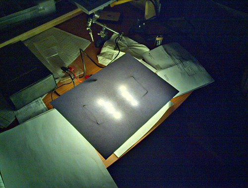
Of course, those pictures don't really convey the quality of the light - although they're HDR (taken with Bless N900) so they're not utterly terrible.

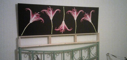
I'll need to play around a bit to see if I can/should use lower value resistors and get the LEDs brighter - they could take a higher current, but I need to verify that the voltages and currents used aren't going to be a fire risk, and look into whether higher current might give a significantly shorter LED lifespan - although this is probably a good point to find a canvas (or some similar looking material) to go on the front...

Light Canvas - LEDs 1: Known Unknowns

This is the more complicated part; or at least I have little idea what I'm doing when it comes to electronics. I know basic theory (e.g. Ohms law), and what various components do, but - so far - no practical experience beyond giving glowing red eyes to a toy raven.

Nevermore!


The electronics for this shouldn't be too tricky though, as it's all simple analog circuits, with no digital components. The plan is to have:
  1. A mains power source (I don't want the hassle and inefficiency of batteries), connected to an input socket in the frame, which itself connects to...
  2. An on/off switch, which connects to...
  3. A linear fader, to control brightness of...
  4. A bunch of LEDs, set up to give an even glow through the canvas (some subtle pattern would be acceptable though).
So, onto the known unknowns:
  • What voltage and amperage should the power source provide? It'll depend on the number and specification of LEDs  it'll be supplying - which I don't know yet. I'm thinking 12V is a fair place to start, and conveniently I've got a 3.5 - 12V adapter to prototype with.
  • I've got a little toggle switch of the type I want to use, but don't know what power it's rated for.
  • The fader could be a potentiometer - or might need to be something else, if the electrical load is too high for a pot. I bought a mixed bag of pots to play around with a while back, and it contained just one linear fader - hopefully it'll be suitable.
  • LEDs - this is the biggest area of uncertainty. There are lots of LEDs with differering specifications available, and I don't know which type and how many I'm going to need for the canvas to glow like I want it to. Aspects to consider:
    • Brightness (enough to shine through the canvas)
    • Viewing angle (wider is better, as I want an even glow, not visible bright points)
    • Number of LEDs to use (more at lower brightness would give more even illumination)
    • Clear vs diffuse finish (at last, an easy one - diffuse)
    • Configuration - rows and columns, random distribution, or some other pattern?
    • How to choose and wire up the right combination of LEDs?
    • Cost - no need to start taking out loans for a hobby...
I think this a fair example of too many choices, not enough knowledge, so I decided that the only way to get started was to just buy some LEDs and fit everything else around that.

Time passing whilst I researched LEDs will be represented by this post ending, and a new one starting...

Wednesday 22 December 2010

Light Canvas - Frame

I tend to think about all the different aspect of a project (in this case, frame, LEDs, canvas) at roughly the same time, gradually figuring out how each part will work, independently and together with the others. That would be an utter nightmare to write up though, so these posts will mainly focus on one aspect at a time. Let's start with the easy one: the frame

This is relatively simple - I know the dimensions of the canvas print (135x45cm), so I know I want my canvas to be 135x15cm.

I little research suggests that getting a pre-built frame this size will be difficult or expensive. To be honest, most of the research was watching YouTube videos on stretching canvases. Woodworking is kinda fun, so I elected to make this myself.

After a while trying to think of a way to add a bevel to regular planks (to make sure the canvas doesn't have lumps due to the frame, I realised I could simply use a simple beveled architrave.

The frame is simply two horizontal and two vertical pieces, glued and nailed together with mitre joints, plus vertical braces inside for strength.
Cutting a mitre joint

Cutting a mitre joint with a plastic mitre box wasn't very accurate - I ended up sanding down the cuts, and hoping that glue would make up for where the surfaces didn't quite meet up.
Mitre joints

Positioning the braces was one of those things where it was totally unclear how many were needed and how to space them, until the four frame pieces were laid out on the floor, at which point it was obvious that two braces at thirds of the width would be ideal. The braces are at the back of the frame, so the shouldn't stop light bouncing around the inside of the frame too much - I want the whole canvas to glow, rather than having several compartments. Here's all the pieces laid out (but not glued or nailed):
Lined up

Also in that pic is a large piece of fibreboard from the Ikea clearance corner - thanks to H and Bic for letting me bring it back with us :-) This will be cut down to size, have the LEDs mounted on, and will be screwed onto the back of the frame.

In keeping with family tradition, my place is full of tools and materials in progress during all this:
Workshop

Ideally I would've used some corner clamps to ensure that the frame was square when I glued the pieces together - but I don't have any, and the local DIY shop didn't have any. Instead, I lined up the pieces to a roofing square that I bought for the cupboard project, PVA glued them all, then nailed them all (with pre-drilled holes). The braces needed a bit of encouragement to keep them in the right place whilst waiting for the glue to cure.
The Clamps

Cut the fibreboard to size, and that's pretty much all the woodworking finished!
Glued and nailed
In position

This is all about white light, so the frame gets painted with a matt white, to reflect as much light as possible, without specular highlights.
Painted

I'll need to make some modifications to fit electronics, but the frame is done for now.

Light Canvas

Another new project! This one started around October, and is a result of three different threads coming together:
  1. I bought a canvas print for my bedroom, a rather nice false-coloured X-ray photo of flowers (probably based on Nick Veasly's work).
  2. 20101026_001.jpg
  3. I need a decent bedside light to replace the rather inelegant broken anglepoise I use at the moment - and preferably something dimmable so I have the option to introduce myself to the day gently.
  4. My guitar lights project (more on that later) has been stalled for around two years, and I could do with a simple LED project to learn and gain some experience with electronics.

The predominantly black canvas immediately suggested a short, wide white canvas emitting white light. I think it could look very cool, and give a nice diffuse light to the room through a rough canvas texture. Including a fader will allow me to control how bright it is.


The basic design is:
  • A wooden frame the same width as the print, but a third of the height. I was vaguely thinking about the rule of thirds when I chose that height, but mainly it was a good fit for the space between the bedhead and print.
  • White LEDs in the frame, with on/off and fader controls, and power supplied via an external switched adaptor (e.g. a typical wall-wart). The LEDs might need some sort of diffuser so the canvas emits light reasonably uniformly.
  • A white canvas stretched over the frame. Obviously, this needs to be thin enough to let the LED light through, but be thick enough to be durable. It should have some texture, for the aesthetic.


From that design, there are a lot of details to work out, starting with:
  • What LEDs do I need? How many? How should I arrange them? What rating power supply will they need? How do I wire it all up?
  • Do I really want canvas - what other options are there?
  • How do I get the frame? Buy pre-made or construct it myself?


Stay tuned for answers to all these questions and more...

Monday 6 December 2010

You gets what you pays for

I bought three webcams matching one I already had, for a total of £16 off eBay.

The good new is they all work.

The bad news is that they can't all work at the same time, as they saturate the entire USB bandwidth.

I now know that cheap webcams send a raw stream of video frames over the wire, whereas more expensive ones compress it (with mjpeg or similar) before sending it over the wire. I now also need to buy more webcams - but more expensive ones.

Bugger.

Friday 19 November 2010

Webcam videowall

So - a new project. Actually an old one (circa 2008) that I'm making a new start on - a webcam videowall:


When I saw Radiohead at Victoria Park as part of their In Rainbows tour, I was quite taken by their visual show - a big rig of LED columns, and video screens. "It'd be cool to do something like that for a Witches gig", I thought.

I'd messed around a bit with freej, and made some progress, but the interface was a bit of a hassle (or rather;I was too lazy to learn it), and I only had one webcam, so that stalled.


Fast-forward to a couple of weeks back, and using the magic of the GStreamer framework on Linux, a couple of cameras borrowed from work, and some essential help from the GStreamer mailing list, I can feed four webcams into one video stream, using this command:

gst-launch-0.10 v4l2src device=/dev/video0 ! video/x-raw-yuv,width=320,height=240,framerate=30/1 ! alpha ! queue ! videomixer name=mix ! ffmpegcolorspace ! \
  xvimagesink sync=false \
  v4l2src device=/dev/video1 ! video/x-raw-yuv,width=320,height=240,framerate=30/1 ! alpha ! videobox left=-320 border-alpha=0 ! queue ! mix. \
  v4l2src device=/dev/video2 ! video/x-raw-yuv,width=320,height=240,framerate=30/1 ! alpha ! videobox top=-240 border-alpha=0 ! queue ! mix. \
  v4l2src device=/dev/video3 ! video/x-raw-yuv,width=320,height=240,framerate=30/1 ! alpha ! videobox left=-320 top=-240 border-alpha=0 ! queue ! mix.

All the programs needed to make this work are available through Ubuntu's package management, so it was dead easy to install.

The Scene:


The Stream:


The cameras producing the top two corners are much older than the bottom two, hence the poorer quality picture.

I found GStreamer to be a bit of a pain to get started with - it's easy to get something simple running by following examples in the documentation (like showing one webcam), but more complicated pipelines are tricky for the newbie as it can be hard to work out why a pipeline won't run.

Still, that's what learning is all about, and there is plenty of documentation, and a very helpful mailing list (thanks!) - it's just quite complex, so don't expect to pick it up straight away.

Next steps will involve looking at:
  • Performance (some cameras are very laggy, which might be due to the cameras, or might be GStreamer - I don't know yet)
  • Different layouts
  • Filtering the videos to make them look more interesting.

Wednesday 13 October 2010

Anyone Can make a music documentary - but it won't be cheap

How To Wake Up

Oxford is mostly known for the University, it's buildings, and Morse - but it has produced some important bands over the years, with probably Radiohead and Supergrass being the most widely known.

Anyone Can Play Guitar is Jon Spira's independent documentary film about 30 years of the Oxford music scene - bands who made it to international stardom, bands who didn't (and why), and the unique music community in Oxford that fostered them. The international impact of (at least) Radiohead warrants a look at Oxford's people, bands, scene - and how they faired with the music industry, so I hope you might see your way to help fund it!

I met Jon through my own small part in the scene, and know him as a scriptwriting teacher, short film and music video director, and owner of the late great Videosyncratic video rental shops - but more importantly here, as a passionate fan of music and film, and I can't imagine anyone better suited to a film about Oxford music than Jon.

Joy Through Work

Around May 2007 local venue The Zodiac closed, prior to AMG converting it into The Carling Academy. The demise of this key fixture of the scene was Jon's prompt to interview band members, film gigs, and collect as much other footage of the diverse bands as possible - so he could tell the story behind it all.

Three and a half years on, the film is yet to be released - even though the main content of the film (sound & video edit, narration) has been finished for a while - it still needs some capital to finish it:

  • a cash injection of £10k for the sound mix and picture grade before it's actually a finished film, and
  • about 30k to legally clear all of the music and footage.
(Initial quotes were £20k for the sound and picture, and up to £60k for music clearance - ouch! Happily, other work Jon completed since finishing putting the film together has attracted interest from people who then saw the film and wanted to help get it finished.)

Jon is pursuing crowdfunding at indiegogo (please visit and contribute some funds!) for the £10k to finish the film ($15k on indiegogo), and once that's done he'll have something he can actually sell to cover the £30k for clearances.

As usual for this sort of crowdfunding there's a range of funding options you can choose from; starting at a credit on the DVD for $15, up to $800 for Executive Producer credit, vip tickets to the premiere, a copy of the dvd, and a poster signed by Jon and some of the bands/artists featured.

Got It Made

Crowdfunding permitting, the film is approaching completion. I would like to have a closer look at the finances but if I spend much longer on it, this post will never be finished. I'll just quickly mention the some key aspects...

Funding

A rough breakdown:
  • Jon and others' personal investment
  • Camera, lights bursary from OFVM
  • Sound mix - crowdfunding
  • Picture grading - crowdfunding
  • Rights clearance - to be funded via distribution rights
Of course, at an estimated £30,000 to £60,000, the big cost is music clearance, which has a whole mess of copyright issues to itself.

Not funding:

  • UK Film council
  • Screen South
  • European arts funding
Jon's blog describes some of his less than satisfying experiences with funding of film and TV projects, and the UK Film Council, in particular.

Tango Borracho

To wrap up - I'm really looking forward to seeing the film (and gutted that I didn't see the OX4 preview as I was already busy), and you should support it. Shame I don't have a spare $800 lying around - it'd be nice to have an Executive Producer credit!

This post was all put together from chats with Jon, reading his blog, and general Oxford music stuff on the web. Anything wrong in it is probably due to me mis-remembering - or plain imagining - conversations. If you spot something wrong here, please let me know in the comments.

Finally - it's cheesy I know - but the headings are all names of tracks from some of my favorite Oxford bands; go and listen to some great music!

Monday 4 October 2010

How to tell if your representative represents?

When I previously emailed my MP, I hoped that he would try to learn about the subject.

Today I received his response:


Dear Mr Balch

Thanks for the email.

I have written to the Secretary of State for Business, Innovation and Skills taking up your concerns.

I will also liaise with other MPs concerned about this,

Best wishes,

Yours sincerely

Rt Hon Andrew Smith MP


Now it may be that the Rt Hon Andrew Smith MP actually has tried to learn about the issues I raised, and has formed an opinion about them. You certainly can't tell from that letter though.

Hopefully I'm just being cynical and he actually is pursuing the issue...

This was very cool

Plaid + Southbank Gamelan Players

a gamelan arrangement of Aphex Twin's Actium

Wednesday 15 September 2010

Just emailed to my MP...

Here's what I just emailed to my MP:

Dear Andrew Smith,

Following on from our contact in March this year regarding the Digital Economy Bill (now Act)[1], it transpires [2] that consumers - via ISPs - will be expected to prop up the business model [3] of a devious, manipulative, and profiteering music industry [4].

Asides from the insult to democracy that was this ridiculous Bill's journey to an Act [5], I find the plan of spending money on bureaucracy and lawyers for no public benefit utterly disgusting, and expect you to work toward the repeal of sections 11-18 of the DEA.

Unfortunately your previous responses have given me no confidence that you have any understanding of the damaging results the DEA will have for individuals [6] and the information economy - I hope that you will read the referenced articles, and further hope for an enlightened response...

Yours sincerely,
David Balch

References:
[1] http://en.wikipedia.org/wiki/Digital_Economy_Act_2010
[2] http://www.bis.gov.uk/assets/biscore/business-sectors/docs/o/10-1131-online-copyright-infringement-government-response
[2] http://www.zeropaid.com/news/90729/uk-isps-unfair-consumers-must-pay-to-protect-entertainment-industry-profits/
[4] http://www.theroot.com/views/how-much-do-you-musicians-really-make?GT1=38002
[5] a shocking lack of understand was demonstrated. http://www.guardian.co.uk/technology/2010/apr/08/digital-economy-bill-passes-third-readinging
[6] e.g. http://www.guardian.co.uk/media/2010/apr/12/digital-economy-bill-households-piracy
I heartily recommend everyone else do something similar with their MP.

Wednesday 23 June 2010

Final finish

Everything thus far unpainted gets a coat, and the visible bits of the shelves get a second coat, and are left to dry.

A quick sand down the top and front (drawers and fascia), and then a second coat of paint for a smoother finish (apparently).

Drawers with second coat of paint

It might turn out that the insides of the drawers will need a second coat, or the commonly visible parts need a third - but I can always go back to it if that's the case. Probably not though.

So that's the cupboard done - de-shelved, re-shelved, and drawer-ed:

The whole cupboard

Flat front

Everything painted and in place.

Of course, the cupboard is now mostly full with all the tools I bought in order to fit it out!

With stuff in.


Job's a good'un :-)

Completing the chest

With the drawers in the framework, there are a few holes to fill - namely the top, and the gaps on either side of the drawers at the front. That involves getting more wood though, as I'm lacking single pieces big enough to cover the wider gap on the front right side. I figure I'll try and get a suitable off-cut from the DIY store,

The top might be filled with a piece of plywood from one of the old shelves, unfortunately it's not long enough to reach the front of the drawers - and (because the cupboard is not square) will need to be at an angle. The pic below shows the sheet of plywood square with the back and sides, but the front has a gap larger on the right than the left:

Wonky cupboard

I have a couple of options here: either get a new piece of wood for the top, or fill some space at the back so the existing sheet can come forwards.

Whilst considering that, I drill, saw, file, and sand handles into the front of each drawer - just a beveled hole about the width of my hand. That's the last major cutting for the drawers, and by this point I'm a little bored, so they're probably a bit rougher than they should be. Never mind, the project is getting pretty close to completion - I can now do some finishing work: filling nail holes and gaps with wood filler, then painting using the same paint used on the cupboard (which was left over from the previous owner's DIY). It's beginning to look presentable.

A trip to my brother's to lend him a tent revealed that he had a load of offcuts from his shelving project (definitely a family trait). I found a suitable piece and nabbed it, and it took very little to cut them to site and nail them in place. With the completely flat front it looks ok - not neat enough for the modernist masterpiece I originally envisioned, but pretty fair.

Painted drawers, and fascia


I decide to go with re-using the materials I already have for the top, and with a bit of sawing and fiddling, it sits quite well:
Painted drawers, fascia, and top


Next up, final painting...

Drawers - part 3: Assembly

The box joints weren't especially close, so would never hold the drawers together by themselves. To make sure they didn't fall apart, I glued the joints, and then nailed them as well, recessing the nails with a nail punch so they wouldn't show in the final result.

The first drawer assembled


The last drawer came together like this (shown at x15 speed):


It even fit the framework:

The first drawer fits!


Alternating between routing and assembly, I put all four drawers together and - with some judicious filing of edges got them to all fit in the framework quite neatly, which was nice.

All drawers assembled

Coming up in the next post, fascia and top...

Drawers - part 2: Routing

Ok, so the Dremel router attachment was delivered and I got back to work. This turned out to be quite tedious, in a classic (not the) right tool for the job way.

The router was needed to make dado joints (simply, straight grooves) on the back, front, and sides of the drawers, and two rabbet joints on the front piece to help fix it to the sides. That's six cuts with the router per drawer, time four drawers is 24 router cuts.

Technically routing with the Dremel worked, but it took a long time to make each cut, as it wasn't powerful enough to go the full depth in one pass - typically needing 5 passes. By the last cut, it took me about 15 mins, earlier ones had taken longer whilst I was getting used to the process and tool.

Here's some video of the last dado, at 15x speed.


Admittedly it would have been quicker if my workbench wasn't so ramshackle, but then again - if I had a router table it would have taken about 5 seconds per cut...

I assembled the first drawer before routing all the parts, so what I learned while assembling it could feed into the next set of cuts. The main point was making sure that all the dado joints lined up well, by combination of measurement with a ruler, and direct comparison of one bit of wood to another.

Assembly coming up in the next post...

Wednesday 16 June 2010

Assembling the framework

Here's the framework assembly video I mentioned in Framework.


Monday 31 May 2010

Tesla be damned

So last week I went to the Lake District for a few days holiday with my chum Nick, and we had a jolly time. It's a beautiful area, and the weather was mostly nice - with one notable exception...

On Wednesday we went for a walk up Barrow Fell, near Keswick - described in the local blurb as "of modest height at 455 meters, there are excellent 360 views from the summit, a great reward for not too much effort". Just the job.

It had rained earlier in the day but as we made our way up there was a nice bit of sun peeking out from between the clouds. There was even proper bright sunshine just as we got to the top :-)

After about 5 mins at the summit, sharing pleasantries with another walker, taking pics and having a bite to eat, some grey clouds came in from the southwest and it started to rain.

Barrow Fell summit
Grey clouds approaching...

Suddenly there was a BANG and flash of thunder and lightning, and what felt like something hitting my head. Nick had the same sensation hitting her leg (she was sat down). We both saw this as our cue to pack up and begin our descent. Fast.

At first I thought "That can't have been lightning", but Nick was pretty convinced, likening it to being hit by a big hailstone. She had been sat on a backpack/seat made with a metal tube frame, so might've had more of a hit.

We're heading down the fell as quick as we can, saying things like: what was that? were we really just hit by lightning? should we ditch the backpack? and thinking that a full on lightning strike could some serious damage to either/both of us.

The rain is quite heavy by now, and then there's thunder and ZAP! we get hit again. It wasn't painful as such, more alarming - simply a shock, and a strong static shock on my head. An electroshock therapy taster session.

A quick mental check and I figure that I don't have much metal on me, although I'm a little concerned that my new phone might have been fried. Is my head feeling funny, or is it psychosomatic?

ZAP! we're hit again. This is ridiculous - surely we're going to get hit by a real bolt at this rate! Can we move any faster!? The other walker showed us the stability advantage of walking poles, gracefully overtaking us as we scrambled down.

ZAP! we're hit again, and I'm sure I saw a hair-thin arc of lighting just in front of my head. The walker got hit as well, doing that hand shaking thing when you get a static shock.

I double checked my baseball cap and found that actually does have a metal stud at the centre - ideal for a lightning conductor to my brain. I took it off and strapped it to my bag.

By this point we were highly motivated individuals, moving quickly down toward the tree line near the bottom of the fell. The atmosphere feels less close now, and we reach the bottom without further shocks. I feel a bit nervous about going under a tree to cross a stile, but it didn't get struck.

The rain stopped and, once we got over the stile, we began to catch our breath, although it wasn't until we were sat in my van down that we could really relax and think about how it could've become life-threatening - hell, it was life-threatening, just with more emphasis on the threat part.

The scary thing, aside from thinking that we might get fried at any moment, was the speed it changed from a lovely day to a dangerous storm, and there's nothing we could've done to prevent or predict it. A small reminder that in spite of our apparent mastery of our environment, we don't really control anything.

A quick check reveals no burns on our heads, and Nick hasn't suddenly got a streak of white hair. Maybe my head feels a little funny but it's faint enough that I'm not sure if I'm just imagining it, so it's probably not serious...


Next on the day's agenda - kayaking on Derwent Water, where we find ourselves irresistible to polystyrene cups in the reception. I suppose for a minor lightning strike, you only get a minor superpower. The storm cleared away and we went on the water without any more shocks. Which was nice.


Later on via my chum Claire, I find that four people were injured by lightning strikes (none seriously) in the same storm, on three other hills approx 2-4 miles from us. A lucky escape!

Wednesday 19 May 2010

Drawers - part 1

I actually did more planning for the drawers before building the framework, but didn't want to disturb the narrative ;-)

I measured the cupboard and considered how much clearance the drawers would need from either side to ensure there wouldn't be any problem opening them, then rounded the remaining space down to a convenient width of 520mm:

Drawer plan

The sides will be shorter than the gaps; the back panel will be slightly tall (a lip at the top), to prevent the drawer being pulled out accidentally; and the front panel will cover half of the framework horizontals above and below it, except the top drawer which will cover all of the top horizontal.

The rear and sides will be connected with box joints, and the front and sides with rabbet joints. The drawer bottom will use dado joints, which will be get nailed and/or glued as well.

Now I know what sizes I need, I can work out a bill of materials, specifying all the parts I need.

Drawing up plans at home is fine, but has a problem in that you can't be sure what materials will be available in the shop. The online guides to making drawers I read suggested ply for the sides and bottoms - but the shop didn't have thick enough ply for the sides, so I picked MDF instead. Hopefully it'll be strong enough!

Once I got my newly purchased two sheets of ply and three sheets of MDF home, I was able to plan how to get the most out of them. Unfortunately there didn't seem to be a way to waste less, but I did get a bit to use as fascia beside the drawers. Different drawer sizes might have been more efficient, but it would have turned into differential equations, and that would be taking it too far...

Drawer cutting plan

Ideally I'd be cutting all of these bits of wood with a table saw, which would be quick, and should help keep edges straight, distances consistent, and angles correct. I don't think I've got the space for a table saw, even if I did think I'd be able to justify it.

Maybe a circular saw, which would be better than cutting everything by hand saw? Nah, still don't think I can justify it.

I had heard about the Dremel multi-tool, which is meant to do cutting, routing, sanding - you name it - and thought that it would do a lot without needing a lot of storage space. It sounds like it would be adaptable to a range of things I'll want to do for this and other projects (my LED guitar for one).

It should cutting box joints, and routing for rabbet and dado joints - I'll have one. In fact I'll also have the pillar drill accessory which I'm bound to use - maybe even instead of the router accessory.

Well, when I tried some cutting, the shape of it meant I couldn't get the right angle, and the cutting disc snapped (I think that's an intentional safety feature). So I'm back to the hand saws. Sawing the boards by hand didn't take too long, but did require a lot of edge shaving, to square everything up.

The next task is box joints, with tenon saw, hack saw, and file. If it was real wood I'd chisel it, but I expect MDF would split in all sorts of horrible ways.

After one box joint the build stalls for a while, because it feels like I'll be sawing for ever. There may have been a rather entertaining a party and a few nights out that took away some momentum as well. Anyway, a few evenings later the mood strikes me again and in just two evenings I get all the other box joints done, with the ply cut to size for the drawer bottoms as well. Progress :-)

Drawer parts with cuts for box joints:
Drawer parts

Those MDF pieces are missing some important cuts: The rabbet joints where the front attaches to the sides, and the dado joints where the bottom fits into the front back and sides. I haven't the skill/patience do those accurately with just hand tools, so I do need a router.

The Dremel can do routing, but it's too wild to use freehand making a dado joint. Using pillar drill accessory as a router looked risky as well, so I went and ordered the router attachment. On the plus side, waiting for delivery of the router gizmo meant I started writing this stuff up...

Tuesday 18 May 2010

Framework

Ok, the new shelves are in, and I have a load of wood ready to make the framework per my design:
Drawer framework plan

As I want to make some proper joints, I need a few tools - a wood saw and power drill are a good start, but a back saw of some sort would help. I think it was a tenon saw I bought.

I also went on a little diversion here, spending most of one morning re-organising my tools into a tote-style tool bag, and putting screws and nails into separate compartments. I'd be worried about OCD if it didn't pay off by making things easier to find, but it does, so that's fine :-)

Anyway, the frame starts with the outside edges of a cuboid:
Outer framework for drawers

The edges resting on the floor are basically there to hold the four uprights in the corners, each of which have been cut at the bottom so they fit over the skirting board.

The corner joints at the top are a sort of combination of mitre and lap joints. Not the most accurate mitres ever, but the overall sizes lock it in place:
Joint in drawers framework

With the outer edges done, I make lap joints on the four uprights, facing the front and back of the cupboard. These are inset with horizontals going from side to side, which in turn have lap joints and corresponding horizontals going front to back.

To space the drawers from the sides, and for more vertical strength, additional vertical colums are created between the front horizontals, to be kept in place with dowels.

Most of this is in the sketches on the right side of this bit of paper:
Design sketches

Not very well described, but it's late, and I have a video of me on a dry-run putting it together that might show it in a comprehensible manner, in which case I'll post it. Update: Here's the video.

Here are all the framework parts ready to be set in place:
Framework for drawers - parts

And here they are in place, with dowels, glue, and just a couple of screws to make sure it doesn't move:
Cuboard with framework for drawers

I haven't mentioned the two uprights in the middle before; they're screwed to the front-back horizontals, and should stop the drawers fishtailing (as well as giving more vertical strength).
A closer view:
Framework for drawers

Note the horizontals going front to back are slightly inside the verticals - they will be supporting the drawers.

Inevitably, this produced plenty of spare wood and off-cuts - hopefully I'll have use for some of them over the rest of the build, and eventually the remainder can go in someone's BBQ, chiminea, or something:
Off-cuts

Next up - drawers...

New shelves

I got the tool I was waiting for today - W00t! I'll talk about that later, once these posts have caught up...

Back in the chronology of the build, I've got the drawers design looking quite solid, but need to put the replacement shelves in before any of the drawers (while access is clear for my step ladder).

This requires more plans:

Shelves plan

Three shelves, the top one shallower for ease of access, and at a reachable height (for me at least). The other two shelves evenly spaced, of course.

There's usually lots of notation about which way is up, forwards, backwards, etc. in my plans - better to note it than make a stupid mistake, I think.

Disliking waste, I like to make good use of the resources available - i.e. re-use stuff that I've already got. This includes some 6mm plywood from the original shelves in cupboard #1 I can use for these shelves :-) It's a little bit bendy, but I'm providing more support timber than it's original use, and the shelves are slightly smaller so will probably have a lighter load.

One trip to the DIY store for the wood (for this and the drawers framework), followed by lots more measuring (the cupboard isn't quite square), sawing, drilling and screwing; and this is the result:
Cupboard 2 - re-shelved

The ply looks a bit crap in place, next to the pine, but hopefully a coat of paint will make it a bit more respectable.

Monday 17 May 2010

De-shelving

With a design fermenting, the first physical job was to take out the rather crap original shelves. (Odd that they were so rubbish when the rest of the flat was so well presented...)

I forgot to take a picture, but there were three shelves mis-matched sizes, materials, with a tendency to sag, and the higher ones were hard to reach/use. Those came out, along with the few bits of wall plugs I could extract.

That left an cupboard containing only holes and dirty marks (and air). Fill up the holes with polyfilla and give it a coat of paint, and that's a good starting point for the job proper:

Cupboard 1 - de-shelved


With a nice clean slate to work from, I started refining the design with scale plans for specific parts...

The framework:
Drawer framework plan
The vertical posts in the corners have to be cut so they fit over the skirting board, but reach top to bottom so will transmit the load of drawers, contents, and someone climbing up to the floor - no wall fixing, so no chance of pulling the supports out of the wall :-)

The vertical posts inset from the sides also provide support, but more importantly they are the side boundaries for the drawers. Note the bigger space on the right, so drawers aren't blocked in by the door.

The base of the framework:
Plan of drawer framework base

The base and outer pieces of the framework form the edges of a cuboid.

The observant will have noticed that the number of drawers has increased to four - after measuring up three seemed too low for the top of the drawers. It may turn out that four is too high, but hey - more storage!