Showing posts with label white. Show all posts

Wednesday, 30 March 2011

Light Canvas - LEDs 3: Circuit development

It's great what you can learn with some time and t'interweb - when finding time between band, family, and the rest of real life, that is...

This LED wizard (and generally informative site) helped me realise that "forward voltage" is the same as "voltage" as generally used, but relating to correctly wired in components, rather than what's coming out of the power source.

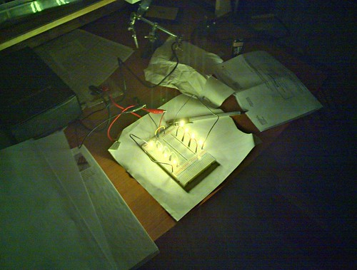
My previous tests were under-driving the LEDs not by current, but by voltage: A 12V source isn't enough to power four 3.3V LEDs - obviously 4x3.3 = 13.2V.

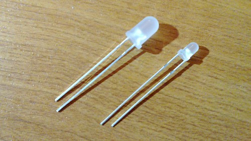
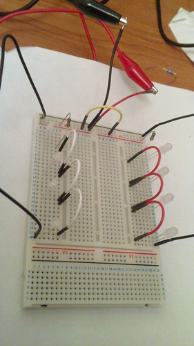
So, rather than four LEDs in series, I can have up to three. Three seems too few though, so after trying some different combinations, I've decided each column will have three 5mm in series, in parallel with two 3mm LEDs in series. This will add up to 420mA, which at 12V is 5.04W.

After a bit more reading I realised that just slinging a potentiometer between the power source and the LEDs wouldn't work (safely at least), as regular potentiometers won't handle power around 5 watts.

Some helpful people on the sci.electronics.basics Usenet group answered my query about what to use instead, and the consensus was to use pulse width modulation - a PWM circuit based on the 555 timer.

Although the intention with the light frame was to do something without that level of complication, it's just accelerating my schedule a bit, as PWM is something I know I'll need for other projects I have in mind.

Here's what I've got so far:
Light canvas circuit v2

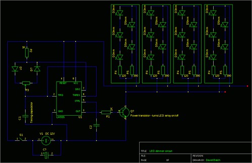
That schematic is missing quite a few important details - like values of the capacitors, diodes, and resistors surrounding the 555 chip. Oh, and there'll be 3 times the number of LEDs.

I've not yet learnt exactly why this circuit should work - specifically how the current flows around the diodes - but the basic principle is that the discrete components around the 555 tell it how long to turn pin 3 on for (the pulse width), with the variable resistor (R3) allowing manual modification of that duration.

Pin 3 goes to the base (B) of a high power resistor, telling it when to allow current to flow between its collector (C) and emitter (E) - acting as a switch between the power and the LEDs.

That gives us: a small (safe) current through the pot, making the 555 turn the transistor on & off, which varies the power going through the LEDs - controlling their brightness. Hurrah!

Now I need to satisfy myself that I understand all the circuit, and figure out the values for those discrete components to get the timing I want, then I can figure out a list of what I need to buy (AKA Bill Of Materials).

There's a possibility that I'll revisit the LED/resistor configuration to see if I can make it more efficient with a higher voltage source, but it's too late in the evening to think about that now :-)

Monday, 27 December 2010

Light Canvas - LEDs 2: Choosing and Testing

After shopping around a bit online, I bought 100 3mm and 100 5mm warm white diffuse LEDs - buying in bulk for this project and the next. As well as size, the two models differ in viewing/beam angle, and brightness. Two types to experiment with is manageable, and should let me play with brightness/diffusion.

One hundred pounds worth of LEDs don't come in a big box...

The LEDs arrive

5mm & 3mm LEDs

(I should've included something for scale in those pics. Nevermind.)

Plan of frame and LEDsOnce I had the frame put together, it occurred to me that three or four LEDs could be put serially in little columns on perfboard, each with their own resistor and connection to the power supply - something like the plan on the right.

Lets remove some unknowns: I want it bright, and nine columns of four LEDs should be pretty good, I reckon.

I've already got wires, resistors, and a breadboard so now I can do some testing.

For prototyping, I attached a couple of crocodile clips to a mains adaptor at it's lowest setting and ran that through a breadboard with one 5mm LED and the recommended resistor, to check that the basics were working, then bumped up the voltage to 12, as I plan to use in the final piece. That worked fine, so I put four LEDs in series and, using an online LED resistor calculator, found a (lower) value of resistor, accommodating the greater voltage drop caused by the additional LEDs (assuming a 2V drop per LED).

If I'm to learn anything here, I ought to figure the resistor stuff out myself, rather than using the online calculator.  For the moment though, I think I get the gist:
  • Power source provides a electrical potential difference,
  • generation of light by each LED is an electrical load, which uses some of that potential, hence
  • voltage drop gives a lower effective voltage over the circuit, hence
  • a lower value resistor is necessary.
I need to do some testing to see how this fits in with Ohms law so I understand it a bit better - but not right now, as there's more hands-on stuff first!

I was quite happy with the 5mm LEDs in a row of four, so did the same with the 3mm LEDs. Here's the breadboard:
Breadboard close-up

...here it is lit up:
Bare LEDs

...with 80gsm paper as a diffuser:
Using 80gsm paper as a diffuser

...and with 160gsm card as a diffuser:
Using 160gsm card as a diffuser

Of course, those pictures don't really convey the quality of the light - although they're HDR (taken with Bless N900) so they're not utterly terrible.

I'll need to play around a bit to see if I can/should use lower value resistors and get the LEDs brighter - they could take a higher current, but I need to verify that the voltages and currents used aren't going to be a fire risk, and look into whether higher current might give a significantly shorter LED lifespan - although this is probably a good point to find a canvas (or some similar looking material) to go on the front...

Light Canvas - LEDs 1: Known Unknowns

This is the more complicated part; or at least I have little idea what I'm doing when it comes to electronics. I know basic theory (e.g. Ohms law), and what various components do, but - so far - no practical experience beyond giving glowing red eyes to a toy raven.

Nevermore!


The electronics for this shouldn't be too tricky though, as it's all simple analog circuits, with no digital components. The plan is to have:
  1. A mains power source (I don't want the hassle and inefficiency of batteries), connected to an input socket in the frame, which itself connects to...
  2. An on/off switch, which connects to...
  3. A linear fader, to control brightness of...
  4. A bunch of LEDs, set up to give an even glow through the canvas (some subtle pattern would be acceptable though).
So, onto the known unknowns:
  • What voltage and amperage should the power source provide? It'll depend on the number and specification of LEDs  it'll be supplying - which I don't know yet. I'm thinking 12V is a fair place to start, and conveniently I've got a 3.5 - 12V adapter to prototype with.
  • I've got a little toggle switch of the type I want to use, but don't know what power it's rated for.
  • The fader could be a potentiometer - or might need to be something else, if the electrical load is too high for a pot. I bought a mixed bag of pots to play around with a while back, and it contained just one linear fader - hopefully it'll be suitable.
  • LEDs - this is the biggest area of uncertainty. There are lots of LEDs with differering specifications available, and I don't know which type and how many I'm going to need for the canvas to glow like I want it to. Aspects to consider:
    • Brightness (enough to shine through the canvas)
    • Viewing angle (wider is better, as I want an even glow, not visible bright points)
    • Number of LEDs to use (more at lower brightness would give more even illumination)
    • Clear vs diffuse finish (at last, an easy one - diffuse)
    • Configuration - rows and columns, random distribution, or some other pattern?
    • How to choose and wire up the right combination of LEDs?
    • Cost - no need to start taking out loans for a hobby...
I think this a fair example of too many choices, not enough knowledge, so I decided that the only way to get started was to just buy some LEDs and fit everything else around that.

Time passing whilst I researched LEDs will be represented by this post ending, and a new one starting...